This section updated 31 August 2008
1 each Power Supply Case with hardware
The coils for the 10 meter filter use one-half PVC schedule 40 pipe and thin wall tubing as the coil form. The form dimensions are listed below.
| Coil # | Pipe Size | Pipe Length | # Turns | Winding Length | Form outside diameter |
| L1, 5 | 1/2 inch | 2 inches | 9-3/4 | 1.00 inches | 0.840 inch |
| L3 | 1/2 inch | 2 inches | 9 | 1.00 inches | 0.840 inch |
| L2, 4 | (see below) | 1-1/4 inches | 3-1/2 | 0.40 inches | 0.620 inch |
L2 and L4 are wound on thin wall PVC tubing with an OD of 0.620 inch nominal.
#14 solid conductor insulated wire.
3 each 36 inches
2 each 12 inches
C1-C6 are 33 pf 3 KV Panasonic P/N ECC-A3F330JGE
C1,C2 (are connected in series)
C3 – 1 each 33 pf
C4 – 1 each 33 pf
C5,C6 (are connected in series)
Mounting hardware 4-40 brass
3 each 1-1/4 machine screws
10 each 1/4 inch machine screws
19 each nuts
5 each washers
Connector labels
This section updated 31 August 2008
The coils for the 10 meter filter use 1/2 inch CPVC and thin wall tubing as the coil form. The form dimensions are listed below.
The coils are wound using #14 solid conductor insulated wire.
| Coil # | Pipe Size | Pipe Length | # Turns | Winding Length |
| L1, 5 | 1/2 inch | 2 inches | 9-3/4 | 1.00 inches |
| L3 | 1/2 inch | 2 inches | 9 | 1.00 inches |
| L2, 4 | (see above) | 1-1/4 inches | 3-1/2 | 0.40 inches |
Note L1 and L5 are wound in the opposite directions so that the leads on the end away from the mounting hole come out pointing toward the input and output connectors. Study the photo carefully. L1 and L5 are also mounted from the opposite end than in the other filters. There should be an inch of lead on the mounting ends which is bent vertical as a terminal. On the connector end there should be about one inch of lead to be use to connect the two series capacitors to the input and output connectors. Trim off any excess after mounting the capacitors. Also notice that for the coils that are not an even number of turns the holes for the wire only end of the form are drilled at 90 degrees to the starting/mounting end.
On L3 the two leads should be about an inch and are formed up as terminals.
The length of the actual coil winding is for reference purposes.
Prepare the case.
Prepare the coils.
Mount the connectors, coil hardware, and lugs.
Mount L1 and L5 first so you can get the internal nut in place.
Mount L3 so you can swing it to get the internal nut in place.
Mount L2 and L4, which are vertical. Mount them so the top vertical lead is matched to the vertical lead on the connecting coil L1 or L5. Use the capacitor lead to bind the two coil leads together before soldering.
Prepare C1, C2 and C5, C6 by soldering two capacitors in series.
Install the capacitors.
There is no shield required in this filter.
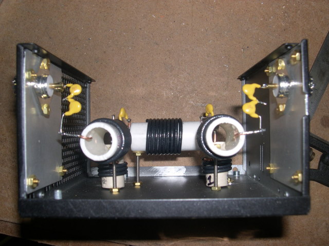
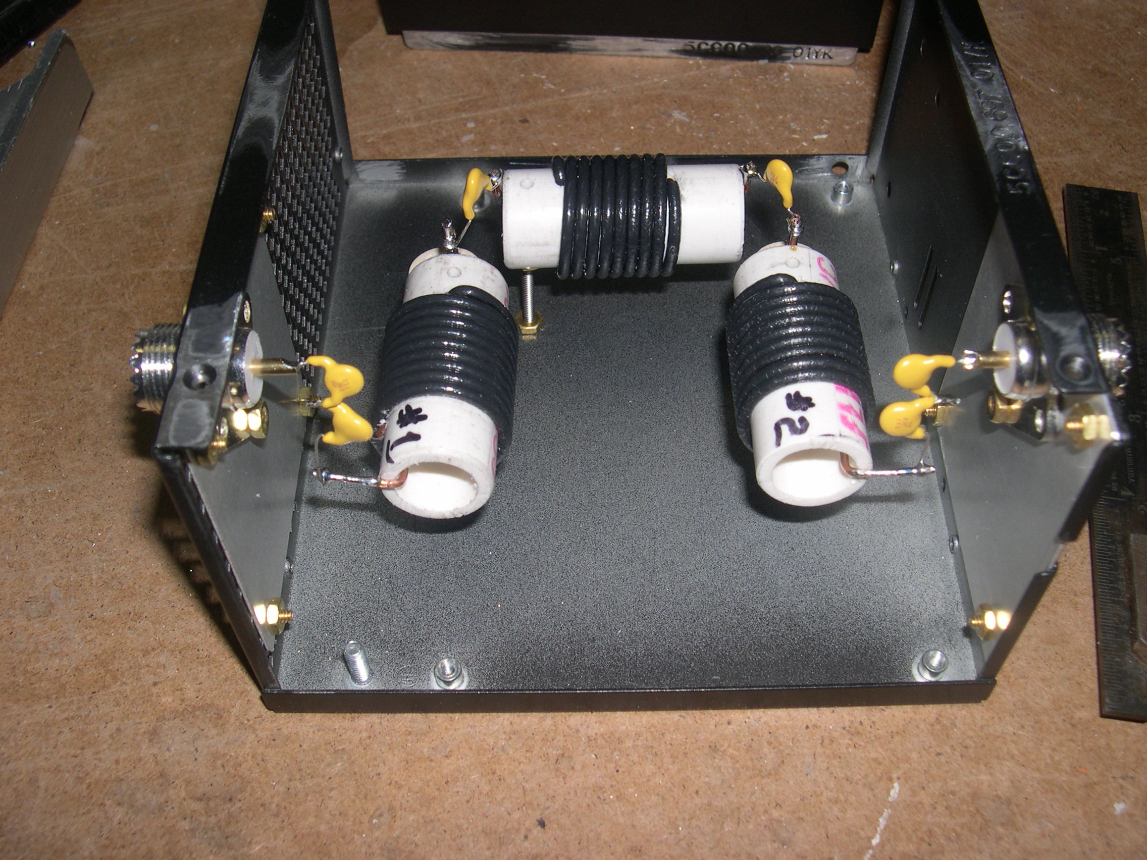
Figure 1: Capacitor and coil view. Note the coil mounting and coil lead preparation by bending around the end of the coils. Also the series connection of capacitors. [high resolution version]

Figure 2: Input/output connector view. Note the direction of the coil windings so coil terminals come out correctly for direct leads to coax connectors. Note the series coils on the input and output are mounted from the opposite end of the other filters. [high resolution version]
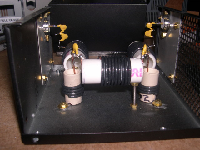
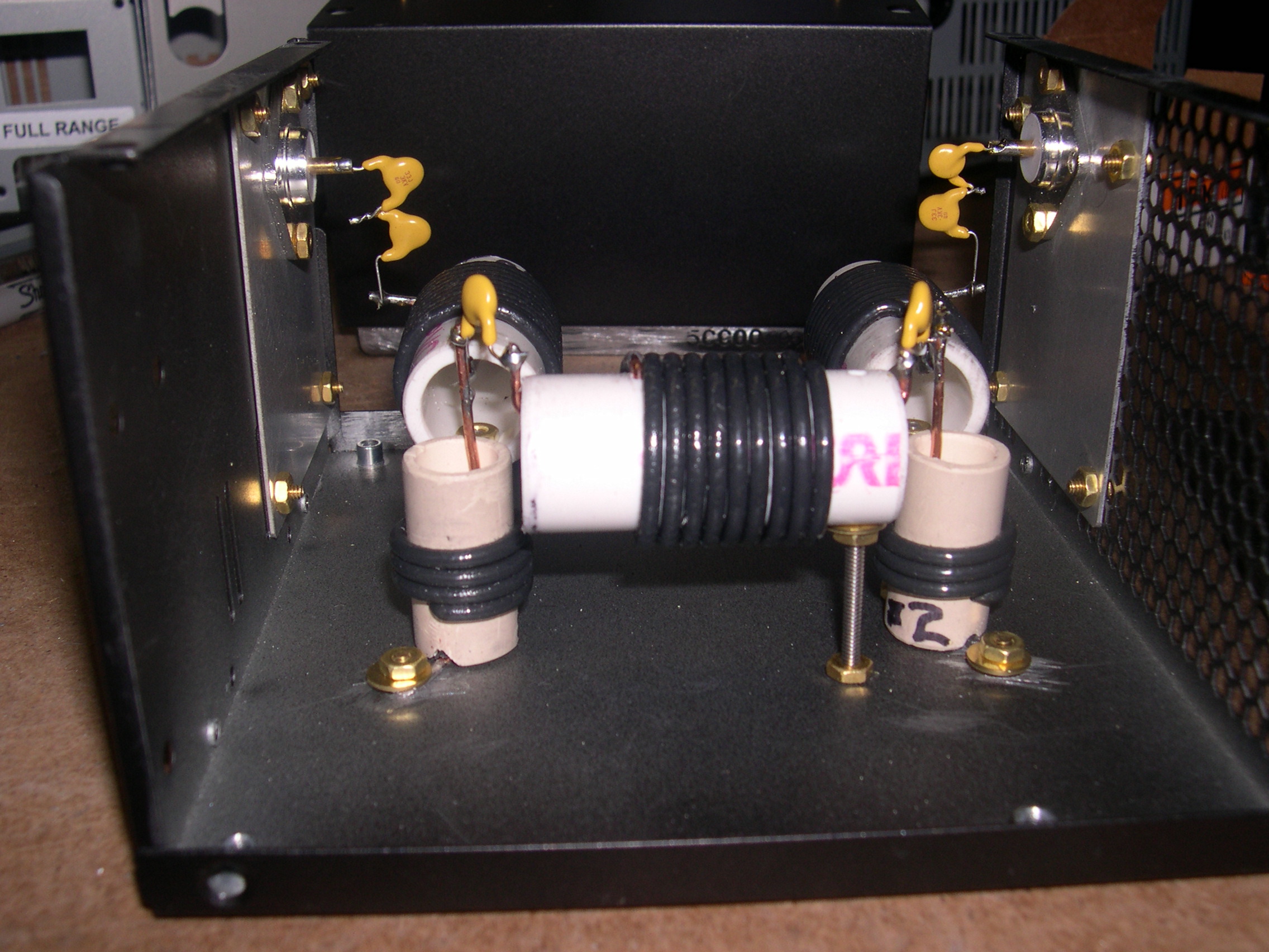
Figure 3: Coil mounting detail. Note the mounting of the shunt coils and the notch to pass the ground lead of coil to the grounding bolt with flat washer and nut. Also the mounting of the series coils on the single bolt. [high resolution version]
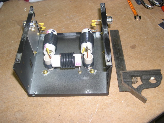
Figure 4: Overall views of filter showing capacitors. [high resolution version]
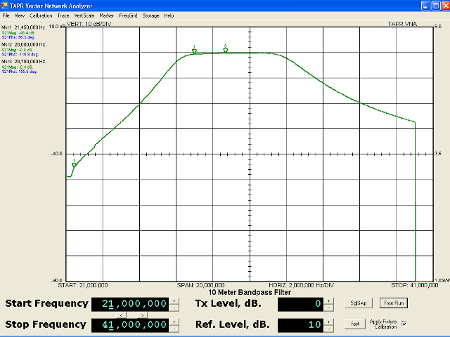
Figure 5: Attenuation vs. frequency [full resolution version]

Figure 6: SWR vs. frequency [full resolution version]
Change History:
| 2008-09-01 | [RRS] | Add this change log. |
| 2008-08-31 | [RRS] | Inductor designations in the parts lists and construction notes changed to match the schematic. Pipe sizes corrected to the standard ASTM "fitting size" designation, separate column added to show the outside diameter. |
Updated $Date: 2008-09-01 21:30:15 +0000 (Mon, 01 Sep 2008) $