This section updated 13 November 2008
3 each Power Supply Case with hardware
The coils for the 160 meter filter use two inch schedule 40 PVC pipe as the coil form. The form dimensions are listed below.
| Coil # | Pipe Size | Pipe Length | # Turns | Winding Length |
| L1,2,3 | 2 inch | 3 inches | 16.75 | 1.70 inches |
| L4 | torroid | T106-2 | 14 | #17 or #18 AWG magnet wire spread over 80% of core |
3 each 11 feet 6 inches #14 insulated wire
1 each 24 inch enameled wire
C1 – 4 each 100 pf 3 KV Panasonic P/N ECC-A3F101JGE, 1 each 56 pf 3 KV Panasonic P/N ECC-A3F560JGE , 1 each 22 pf 3 KV Panasonic P/N ECC-A3F220JGE
C2 – 3 each 150 pf 3KV Panasonic P/N ECC-A3F151JGE , 1 each 100 pf 3 KV Panasonic P/N ECC-A3F101JGE , 1 each 22 pf 3 KV Panasonic P/N ECC-A3F220JGE
C3 – 4 each 150 pf 3 KV Panasonic P/N ECC-A3F151JGE , 1 each 100 pf 3 KV Panasonic P/N ECC-A3F101JGE , 1 each 47 pf 3 KV Panasonic P/N ECC-A3F470JGE
C4 – 5 each 470 pf 1 KV Panasonic P/N ECC-A3A471JGE , 1 each 47 pf 1 KV Panasonic P/N ECC-A3A470JGE
Mounting hardware 6-32 brass
6 each 2 inch machine screws
1 each 1-½ machine screw for standoff mounting
18 each flat washers
18 each nuts
Misc hardware 4-40 brass
20 each ¼ machine screws
22 each nuts
7 each washers
2 each ground lug
1 each 6-32 standoff
1 each torroid core T106-2
Connector labels
This section updated 2 October 2008
The coils for the 160 meter filter use 2 inch schedule 40 PVC pipe as the coil form. The form dimensions are listed below.
The coils are wound using #14 solid conductor insulated wire.
| Coil # | Pipe Size | Pipe Length | # Turns | Winding Length |
| L1,2,3 | 2 inch | 3 inches | 16.75 | 1.70 inches |
| L4 | torroid | T106-2 | 14 | #17 or #18 AWG magnet wire spread over 80% of core |
The length of the actual coil winding is for reference purposes.
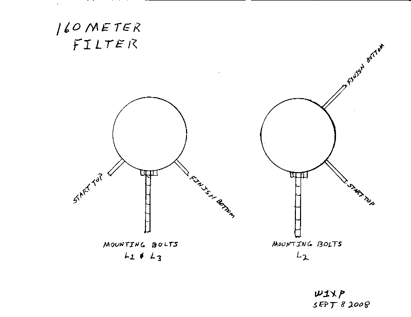
Note: The direction of the winding is important so the ends of the coils come out in the proper place relative to the mounting bolts. See the coil sketch before winding.
Additional Notes on 160 meter filter assembly.
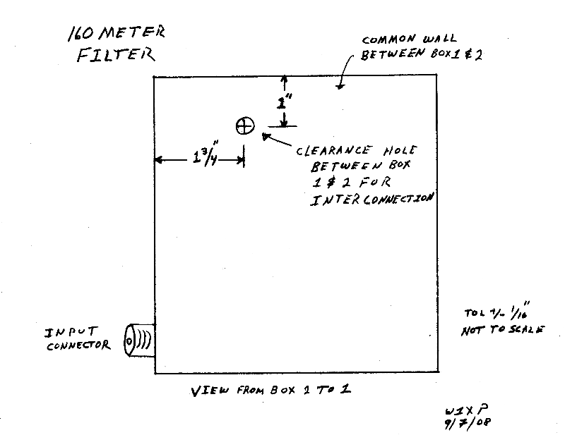
The 160 meter filter is built in three computer power supply cases. Each case has one large coil wound on 2 inch Schedule 40 PVC pipe. There is a forth inductor wound on a T106-2 toroidal core. The filter is built in two halves and for final assemble a lead is feed through a hole in the partition between case 1 and 2. The final connection is then made in case 1, see photos, and the end cover to case 1 put in place.
It is important that the coils be wound in the proper direction so that the coil terminals are located properly with respect to the mounting bolts. A sketch of the coils is included and should be studied before winding the coils. The sketch depicts the relationship between the leads the mounting screws. The expression “top” refers to the end closest to the viewer. Starting the winding at the top and proceed in a clockwise direction to the bottom. The leads are routed from the inside of the core over the end. See reference to notching the core later.
The junction of the coils and the series capacitors is the high impedance point in the filters. For this reason it is necessary to keep this point protected against high voltage breakdown to the case. This is the outside ends of L1 and L3 and the end of L2 on the end closest to case 1. For this reason these leads need to have insulation on them where they pass close to the case. If the insulation has been removed slide a piece onto the lead to protect it from breakdown. Cutting a notch in the end of the coil form to allow the lead to pass around the end of the coil at a greater distance from the case wall is also a good idea.
The leads that pass between the cases are arranged to be at low impedance points in the filter and breakdown is not as big a problem. But be sure the wires have insulation and that there are no burs on the edges of the holes to puncture the insulation.
The three cases have to be attached together in such a way that the circuits can be built and the boxes screwed together since there is no access to the center box once the end boxes are attached. Orient the boxes to take best advantage of openings with consideration that the input and output connectors need to be on opposite sides (see the reference picture). This arrangement allows access to the two end boxes after the center box is finished and closed and uses the cover screws for the center box (box #2) to be used to attach box one and the cover of box two to box two.
When I refer to the base of a box I mean the section that typically had the power supply board attached usually on standoffs. The top of the box is the part that after sliding together typically has four clearance holes for machine screws to fasten the two parts together.
Align two boxes base to base. Secure them together at four places. If the boxes are the same you may be able to use the threaded standoff on one and drill clearance holes in the other. The general solution is to drill four clearance holes through the two aligned boxes and use machine screws and nuts to fasten them together. Drill the necessary mounting holes in the boxes. This prepares boxes two (2) and three (3).
Attach the third section. Align the base of box one (1) to the top of box two (2) which is already joined to box (3). Mark the location of the clearance holes for the screws which attach the cover of box two to the base which is already attached to box three. Drill clearance holes for the screws at the marked locations on box one. The case sketches are looking from the center (#2) box to the end boxes.
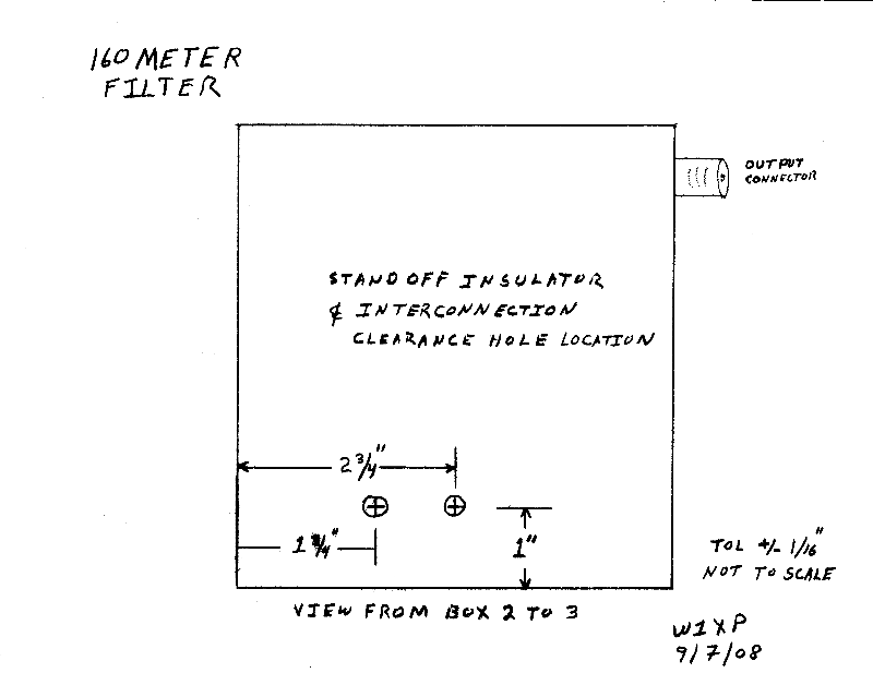
Drill the through holes where indicated for the connection to the circuit in the other boxes. And for the lug that attaches L4 to the chassis.
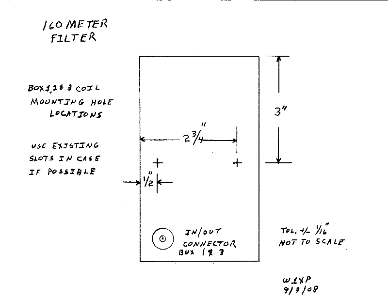
Drill the mounting holes for connectors and coil mounting hardware.
Prepare the coils. The difference between these coils and the previous coils is the free leads need to stay insulated as they are routed near the case sides when installed. This may make tightening the windings more difficult as the stripped wire was easier to draw through the final form hole.
For the capacitors that require two or more in parallel prepare the capacitors by gently twisting the leads one turn and soldering the entire length.
Mount the connector's lugs and standoff.
The components can be mounted in all the boxes now. The interconnecting wire from box three to two can be seen in the pictures running from the base of L2 thru the base of the box and into box three where it serves as a terminal point. The interconnecting wire from box two to box one can be seen attached to the standoff in box two which goes through a hole in the box two cover/box one base. Note these two leads must be insulated as they go through the small holes between boxes.
Install the rest of the capacitors and solder in place.
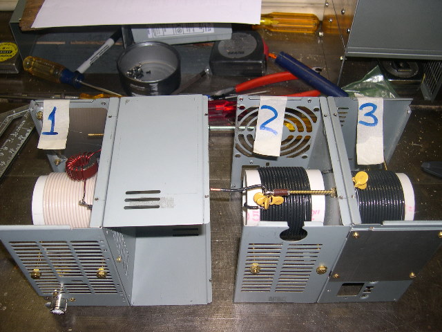
Figure 1: Assembly of the 3 boxes. Note the lead of the coil in box 2 ready to solder through to box 1 when assembled. [high resolution version]
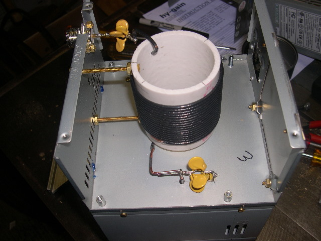
Figure 2: Box 3 coil and capacitor mounting detail. [high resolution version]
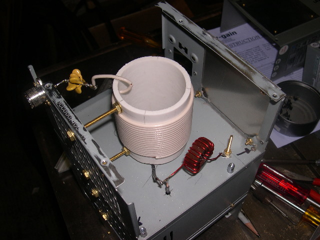
Figure 3: Box 1 coil and capacitor mounting detail. [high resolution version]
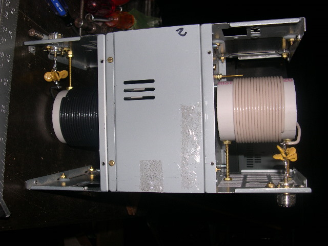
Figure 4: Assembled boxes, with covers off boxes 1 and 3. [high resolution version]
Updated $Date: 2008-11-14 03:13:46 +0000 (Fri, 14 Nov 2008) $